
Address-Event-Representation Tools
Complex systems developed by Neuromorphic Engineers require interfaces to interconnect them and to connect them to PCs for debugging or other purposes. This milestone was the start point for the development of a set of Address-Event-Representation (AER) Tools under the European Project CAVIAR. We are four different partners working together in the design of a neuromorphic vision system totally based on AER. CAVIAR connects the biggest AER chain at the moment [1]. This chain is composed by a 128×128 retina that spikes with temporal and contrast changes [2], four convolution chips to detect a ball at different distances from the retina [3], four object chips to filter the convolution activity [4] and a learning stage composed by two chips: delay line and learning [5]. To make all this vision system possible, a set of AER-Tools or debugging and interconnection purposes are not only useful, but also necessary.
These AER-Tools are divided into 4 different PCBs with 8 different functionalities, depending on the firmware downloaded to them.
CAVIAR PCI-AER USB-AER AER-Switch Mini-USB-AER
Our group (Robotics and Computer Technology – RTC) has developed a PCI to AER interface, taking as a starting point the Rome PCI-AER developed by Dante; two USB to AER interfaces and an AER to AER interface. All of them with Linux and XP drivers and Matlab interfaces.
CAVIAR PCI-AER
To inject and read events to an AER system, using a PC, a bridge between the AER bus and one PC buses is necessary. To obtain the maximum bandwidth the PCI is nowadays one of the best candidates. Our interface differs from the Rome PCI-AER [6] in several characteristics:
- The CAVIAR PCI-AER is not a communications centre and does not have a mapper or a splitter/merger included. This PCI-AER interface is a very fast communication channel (up to 10 Mev/sec vs 1Mev/sec of Rome board) between an AER bus and the PC software.
This interface, shown in figure 1, has the following technical features:
- It is designed around a Spartan II 200 FPGA, with a PCI interface developed in VHDL by RTC, which makes it cheaper and faster.
- It has one AER output bus and one AER input bus.
- There are two FIFOS (input and output) that can save the event information and its timestamp for up to 128 events (output) and 256 events (input).
- Timestamp is relative (distance between consecutive events), but the time controller is able to recovery from protocol induced delays. Therefore, if one event is delayed, the following don’t have to be delayed.
- Configurable resolutions of timestamp from 30 ns to 480 ns per timer tick.
- Support of PCI mastering.
- XP and Linux drivers available and Matlab interface.
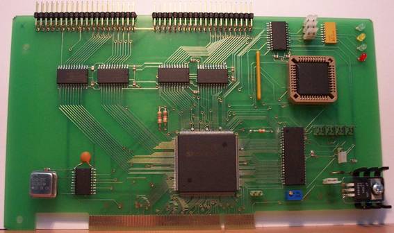
Figure 1: CAVIAR PCI-AER interface.
USB-AER
A more portable, easy to use and versatile interface is always valuable. This interface is also designed around a Spartan II 200 and a Cygnal 8051 USB microcontroller, which make it fully configurable. The maximum throughput of the USB interface is 6 Mbits/sec (~187Kevents/sec), which limits the use of this interface for event based communications between the PC and the board. Therefore, this interface receives the control information or frames (bitmaps) from the PC and uses hardware based frame to AER transformations to produce AER events.
The integrated 2 MB 32bit wide SRAM, the SD/MMC slot, the USB connector and the two AER connectors, as shown in figure 2, make this board very attractive to develop an interesting set of AER-Tools. Some of these tools are dependent on a PC while other are not:
- PC dependent: the FPGA firmware is downloaded through the USB bus and the commands and data are communicates through USB.
- PC independent: the SD/MMC memory card has the firmware stored and the microcontroller downloads it to the FPGA without any PC.
This board currently has several available firmwares whose functionalities are the following:
- AER generator: A frame (bitmap) is downloaded from a PC and through a method for synthetic AER generation [7], a sequence of events is generated and sent. One of the possible methods follows a Poisson distribution of the events [8].
- AER Mapper: there are available firmwares for 1-1 mapper, 1-N (with N from 0 to 8). A probabilistic version which assigns a probability to each of the possible output events associated to an input event is also available.
- AER Frame-grabber: two kinds of firmware are available: USB frame-grabber (32×32 and 64×64 image size) and VGA frame-grabber (64×64 and 256×256 image size that uses an additional daughter board: AER-VGA).
- Datalogger and Player: uses the 2 Mb SRAM to capture up to 512Kevents with 16bit relative timestamp resolution. And it also plays back a sequence of events stored in the SRAM. This sequence is received from the PC via USB.
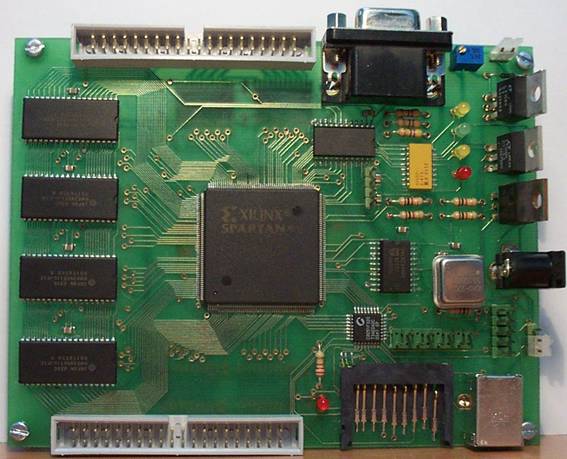
Figure 2: USB-AER interface.
AER Switch
With the mentioned interfaces we can connect a PC to an AER chip and an AER emitter to a receiver. The last necessary interface should be able to connect many to one and one to many chips or PCs. This interface is called AER-Switch and can perform two different operations:
- AER Splitter: One AER input is routed to up to four AER outputs. These outputs can have the input traffic replicated, or be assigned to different ranges.
- AER Merger: up to four inputs are joined to one output. It can add bits to identify the input channel if necessary.
The AER switch is based on a Xilinx 9500 CPLD. It has 5 AER ports (one input, one output and three bidirectional ports).
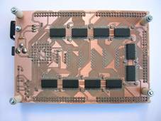
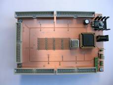
Figure 3: AER-Switch interface.
Mini-USB-AER
For small event rates and simple operations, a reduced version of the USB-AER has been developed together with Toby Delbruck from INI. This interface allows connecting an AER bus to a PC in both direction (sequencer or monitor). The PCB is based around a Cygnal 8051 microcontroller, with no FPGA.
A good software kit that fully supports this board as a monitor is available.
The supported event rate is around 100Kevents/sec.
A new version that supports High speed USB2.0 and is capable of event rates up to 8Mevents/sec is currently under test.
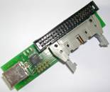
Figure 4: Mini-USB-AER interface.
References
[1] R. Serrano-Gotarredona, M. Oster, P. Lichtsteiner, A. Linares-Barranco, R. Paz-Vicente, F. Gómez-Rodríguez, H. Kolle Riis, T. Delbrück, S. C. Liu, P. Häfliger, G. Jimenez-Moreno, A. Civit, T. Serrano-Gotarredona, A. Acosta-Jiménez, B. Linares-Barranco, AER Building Blocks for Multi-Layer Multi-Chip Neuromorphic Vision Systems, NIPS’05, Vancouver, December-2005.
[2] P. Lichtsteiner, T. Delbruck, 64×64 Event-Driven Logarithmic Temporal Derivative Silicon Retina, 2005 IEEEWorkshop on Charge Coupled Devices and Advanced Image Sensors, Nagano, Japan, June-2005.
[3] Rafael Serrano, Teresa Serrano, Antonio José Acosta, Bernabé Linares-Barranco, An Arbitrary Kernel Convolution Aer- Transceiver, ISCAS’06, Kos, Greece, May-2006.
[4] Oster, M., Liu, S.C., A Winner-take-all Spiking Network with Spiking Inputs, ICECS 2004, Tel Aviv, 2004.
[5] H. Kolle Riis, P. Haefliger, Spike based learning with weak multi-level static memory, ISCAS’04, vol. 5, pp. 393-395, Vancouver, Canada, May-2004.
[6] Vittorio Dante, Paolo Del Giudice, Adrian M. Whatley, Hardware and software for interfacing to address-event based neuromorphic systems The Neuromorphic Engineer, vol 2, number 1, March-2005.
[7] A. Linares-Barranco, G. Jiménez-Moreno, B. Linares-Barranco, A. Civit-Ballcels, On Algorithmic Rate-Coded AER Generation, IEEE Trans. Neural Networks. May-2006.
[8] A. Linares-Barranco, M. Oster, D. Cascado, G. Jiménez, A. Civit, B. Linares-Barranco, Inter-Spike-Intervals analysis of Poisson like Hardware Synthetic AER Generation, IWANN’05. Vilanova I la Gertru. SPAIN . June-2005.
Contact:
Alejandro Linares-Barranco and Antón Civit-Balcells Robotics and Computer Technology Lab. University of Seville, Spain. Email: alinares@atc.us.es